

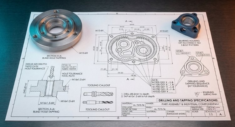
How to Prepare an Engineering Drawing for Drilling and Tapping
An engineering drawing gives a machining supplier the information required to manufacture a component correctly. For drilling and tapping work, the drawing should clearly communicate the location, size, and depth of holes along with the required thread specifications.
Incomplete hole information can create confusion during setup and inspection. Providing clear drawing details helps the machining team understand the component before drilling and tapping operations begin.
Why Drawings Matter in Drilling and Tapping
Technical drawings serve as the primary legal and manufacturing contract between design engineers and machinists. Accurate drawings eliminate ambiguity, allowing CNC programmers to establish correct tool paths, select optimal cutting speeds, and set exact $Z$-axis depth limits. Clear documentation reduces scrap rates, prevents costly tool breakage, and guarantees that finished parts mate perfectly during final assembly.
Hole Diameter and Tap Drill Specifications
Specifying the exact hole diameter ensures proper clearance or thread engagement:
-
Clearance Holes: For unthreaded pass-through holes, explicitly state the nominal diameter along with acceptable fit tolerances (e.g., Close, Normal, or Loose fit per ISO/ANSI standards).
-
Pre-Tap Drill Sizes: While standard tap drill sizes are maintained in machining lookup tables, referencing the target drill size or required thread percentage (typically 65% to 75%) helps avoid misinterpretation on custom alloys.
Hole Location and Geometric Tolerancing
Hole placement must be fully constrained on the drawing to ensure proper alignment:
-
Coordinate Dimensioning: Position hole centers relative to clear, accessible reference datums (edges, centers, or mounting faces).
-
Pitch Circle Diameters (PCD): For circular bolt patterns, specify the PCD, number of holes, and angular spacing (e.g., $6\times \text{ holes equally spaced on a } \varnothing 100\text{ PCD}$).
-
True Position (GD&T): Use Geometric Dimensioning and Tolerancing positional symbols ($\phi$) to define precise true position limits rather than relying solely on linear coordinate tolerances.
Blind or Through Hole Callouts
The drawing must clearly state whether a hole penetrates the part entirely or stops at a specific depth:
-
Through Holes: Indicate with the suffix THRU after the diameter dimension (e.g., $\varnothing 12.0 \text{ THRU}$).
-
Blind Holes: Use the depth symbol ($\boldsymbol{\Downarrow}$) followed by the numerical depth limit. Avoid ambiguous terms like “drill to suit.”
Countersink and Counterbore Requirements
When fasteners must sit flush with or below the component surface, include explicit feature callouts:
-
Countersinks ($\boldsymbol{\vee}$): Specify the major entrance diameter and included angle (e.g., $\boldsymbol{\vee} \varnothing 12.0 \times 90^\circ$).
-
Counterbores ($\boldsymbol{\sqcup}$): Specify the counterbore diameter and exact flat-bottom depth (e.g., $\boldsymbol{\sqcup} \varnothing 15.0 \boldsymbol{\Downarrow} 8.0$).
-
Lead-in Chamfers: A small $45^\circ$ chamfer at the hole entrance should be specified to ease tap entry and prevent raised entry burrs.
Material Specification and Heat Treatment
Machining parameters depend directly on workpiece material characteristics:
-
State the precise material grade (e.g., Aluminum 6061-T6, Stainless Steel 316L, Mild Steel EN8).
-
Indicate any heat treatment condition (e.g., annealed, hardened to 40-45 HRC) prior to machining, as high hardness requires solid carbide taps or thread milling instead of standard HSS taps.
Quantity and Batch Requirements
Including volume details directly on or alongside the drawing context helps the supplier choose the most efficient manufacturing approach:
-
Prototypes / Low Volume: Prototype quantities may be machined using single-point tools or manual multi-setup routines.
-
Production Runs: High-volume orders warrant custom multi-tool setups, rigid tapping programs, or dedicated drilling jigs to lower unit costs.
Tolerance Information
Unrealistic tolerances increase production costs without adding functional value. Apply a balanced tolerancing strategy:
-
Standard Title Block Tolerances: Use global tolerances for non-critical clearance dimensions (e.g., $\pm 0.1\text{ mm}$).
-
Tight Tolerances: Apply specific tight tolerances only to critical features, such as press-fit pin locations or precision bearing bores (e.g., $\varnothing 8.000 +0.015/-0.000$).
Sample-Based Machining and Reverse Engineering
When formal CAD files or 2D engineering drawings are unavailable:
-
Physical sample components can be provided to the supplier for reverse engineering.
-
Key parameters—including pitch, hole locations, and mounting centerlines—are measured using coordinate measuring machines (CMM) or thread gauges.
-
A formal approval drawing should be generated from the sample and signed off before production begins.
Common Drawing Mistakes to Avoid
-
Omitting Thread Class: Forgetting class fit designations (e.g., 6H vs. 6G) leaves thread tightness open to interpretation.
-
Confusing Thread Depth with Drill Depth: Marking only one depth forces the machinist to guess the required drill depth for a blind hole.
-
Missing Datum References: Dimensioning holes from floating or unmachined rough cast surfaces leads to positional errors.
-
Over-Tolerancing Non-Critical Holes: Applying unnecessarily tight positional tolerances to simple clearance holes inflates machining costs.
Conclusion
A well-prepared engineering drawing eliminates guesswork, lowers production costs, and accelerates manufacturing lead times. By clearly detailing hole diameters, true position locations, explicit thread callouts, and depth limits, design engineers provide the exact roadmap required for accurate CNC drilling and tapping operations.



 Users Today : 0
 Users This Month : 1
 Total Users : 2